Boost bleed/purge line

Sekred

1000 Post Club
Member ID
#393
Messages
1,395
Likes
405
#1
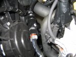
I was scratching around in the engine bay recently and notice something I think is rather strange regarding the plastic piping attached to the intake manifold, inlet tube and intercooler cold pipe.
Let me see if I can explain it in a way people can understand. I have attached some images and you can always go and look at your ST to work out what is going on.
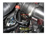
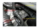
Let me start with the plastic pipe that connects just in front of the MAF sensor. If you follow this line down it connects to the intercooler cold pipe. So when ever the turbo produces boost, boost pressure is allowed to bleed or purge straight back to the inlet tube. The line has an ID of 8mm and the 2 fittings have an ID of 5mm. I would be interest to know what the flow rate would be at 20psi or better still the purpose of bleeding boost pressure off like this.
Teeing into this pipe is what looks like a disc shape one way valve. I pressure and vacuum tested this line and the valve or what ever it is remained closed. From this disc valve the line then tees into another plastic line with one end running to the intake manifold through a check valve just above the throttle body. The check valve allows vacuum into the line only. The other end of this line then runs to an electrical switch and forms part of the fuel tank evaporation system, I think. This part of the system does not concern me it's the constant bleed off, of boost pressure that I find unusual .Anyone got any ideas on the purpose of this boost bleed/purge line.

Slide1.JPG Slide2.JPG


Colin1337

1000 Post Club
Member ID
#586
Messages
1,488
Likes
61
#2
Noticed this when I put my intake on a few months ago. Looks like a boost leak to me, but then again they did design it that way for a reason so who knows...


Member ID
#707
Messages
310
Likes
11
#3
Noticed this when I put my intake on a few months ago. Looks like a boost leak to me, but then again they did design it that way for a reason so who knows...
I think this is what I think


XuperXero

Active member
Member ID
#716
Messages
587
Likes
130
#4
I also noticed this line as well. I thought about blocking it off too, but I have no idea what could result from it. It does look messy. All the extra vacuum lines. There's a couple more under the intake and near firewall and even one connecting to sound symposer... SO... MANY... VACUUM.... LINES.............


XuperXero

Active member
Member ID
#716
Messages
587
Likes
130
#6
OP
Sekred

Sekred

1000 Post Club
Member ID
#393
Messages
1,395
Likes
405
Thread Starter #7
Well I decided to be the pioneer here and block this line off. After all, who wants to waste good boost pressure.
I used a check valve, probably unnecessary but I had it in my box of bits so it won't hurt.
I have driven the car a number of times with no negative effects.

Boost bleed check.jpg


Member ID
#614
Messages
307
Likes
17
#8
You say there are no negative affects, but are there any positives? If not, why do it? I'm not trying to bust your balls, just honestly wondering? Most of this is above my head, mechanically speaking.


OP
Sekred

Sekred

1000 Post Club
Member ID
#393
Messages
1,395
Likes
405
Thread Starter #9
You say there are no negative affects, but are there any positives? If not, why do it? I'm not trying to bust your balls, just honestly wondering? Most of this is above my head, mechanically speaking.
Well the reason I choose to do it is I failed to see the point of bleeding boost pressure continually back to the intake tube.
When ever I make a modification, the first thing I ask myself is, will it have a detrimental effect on the vehicle and then try and think of all the things that can go wrong.
30 plus years of experience in a mechanical background in mining and earthmoving gives me lots of insight, I have seen some mega failures.
Is there any positive effects, certainly. Although the loss of volume though this line is small, the turbo has to work harder to compensate. Think of a hole punched in you intercooler, the only difference is boost lost to the atmosphere and boost lost in a close loop.


RAAMaudio

5000 Post Club
Member ID
#817
Messages
5,268
Likes
927
#10
Maybe it was to help smooth out the big spike and drop off of the torque curve or is part of the 1st and 2nd gear power reduction, or a combination of both........?


OP
Sekred

Sekred

1000 Post Club
Member ID
#393
Messages
1,395
Likes
405
Thread Starter #12
These are nice check valves. I actually used one of these in my oil separator and modified it because I had trouble finding anything in Australia. To attach it, fuel line type clamps would work ok imo.

17.jpg

Fuel line clamps.png


me32

1000 Post Club
Member ID
#848
Messages
1,829
Likes
265
#13
Very interesting. So has this new mod been tested with a data log to see if boost no longer falls or holds longer? Any power gains?


Member ID
#858
Messages
16
Likes
0
#14
Sekred, what are the style of clamps you used on your design? Reminds me of a style that I saw on my VW when I had it.

Its been tested but I do not think anyone has truly data logged this. Any updates sekred from the install until now?


OP
Sekred

Sekred

1000 Post Club
Member ID
#393
Messages
1,395
Likes
405
Thread Starter #15
Sekred, what are the style of clamps you used on your design? Reminds me of a style that I saw on my VW when I had it.

Its been tested but I do not think anyone has truly data logged this. Any updates sekred from the install until now?
There called a Ear clamp or crimp clamp. You can only use them once, to remove I usually cut through one of the ears with side cutters.

Crimp clamps.png


OP
Sekred

Sekred

1000 Post Club
Member ID
#393
Messages
1,395
Likes
405
Thread Starter #16
Very interesting. So has this new mod been tested with a data log to see if boost no longer falls or holds longer? Any power gains?
I haven't done any data logging. I'm not making any claims about power gains, it won't make any difference to the way boost falls away above 5000rpm or so. The fall in boost is the ECU duty cycling the boost solenoid to control turbocharger speed (boost). There would be a number of reasons to reduce boost as the engine approaches it redline, one of them (imo) would be to stop the tiny KP 39 blowing its whistle and popping the compressor wheel which is the most common failure when you continuously overspeed a turbocharger.


RAAMaudio

5000 Post Club
Member ID
#817
Messages
5,268
Likes
927
#18
I use clamps like that in SS but with just one side having the crimp section. I can usually remove them by putting a screwdriver in and twisting if not to tightly crimped.

If I have the right diameter fittings and hose to work with I use my PEX crimp tools and copper rings, nothing coming off when you do that!

I use crimps on all push lock, etc hose fittings now as well, I had so many at one time I got mixed up and used the wrong hose for the fitting, they all look so much the same and not marked...blew an oil line at speed on track, went off backwards....scary but cleaned it up, local racer gave me some SS screw on hose clamps and I was good to go but now, I crimp them all.


RAAMaudio

5000 Post Club
Member ID
#817
Messages
5,268
Likes
927
#19
I have nearly finished building all my own parts, intake to exhaust and porting everything, manifold included, except the turbo, just not worth it as it has to go, I will have a bigger turbo as soon as I can then port it as well.


MOFiST

Active member
Member ID
#661
Messages
724
Likes
74
#20
Thanks for the tip Sekred.
I've got the JS performance SRI on my car and I simply capped their supplied barb fitting. Can't see any reason to leave a closed loop boost leak on the car.


Similar threads


Top