Want to add an electrical circuit to your car, and aren’t quite satisfied with Fuse Taps, T-Taps and other makeshift wiring methods? Look no further!
After a bit of sleuthing, and dissecting a couple of junkyard Fiesta fuseboxes, I’ve discovered how to use the unused fuse slots in the main junction boxes (and where to find new terminals) for a really clean install of those things you want to add to your car, like water/meth systems, dashcams, small subwoofers, etc. I figured it was worth putting together the information to share.
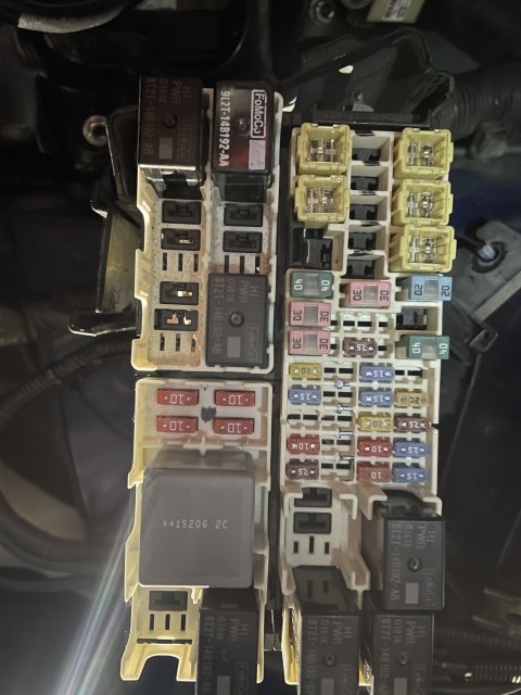
First off. Don’t do what the previous owner of my car did and jam a wire under the unfused “live” side of a fuse blade and call it a day!
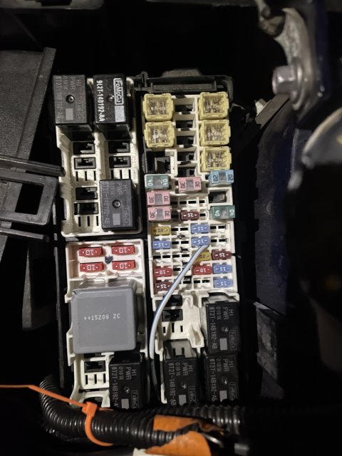
With that hair raising image out of the way, it turns out there are a few unused fuse spots in both the main “battery junction box” (BJB in the electrical diagrams) in the engine bay, and a couple in the “central junction box” (CJB in the diagrams) behind the glove compartment. After dissecting fuse boxes and It turns out that both of them use Yazaki style open barrel crimp spade terminals that are available on Mouser which are listed below.
I chose to install my circuits in the engine bay BJB and run through the firewall seal for several reasons:
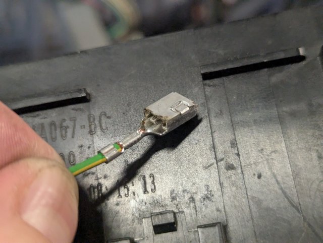
First off, the part numbers. (All the terminals are between 10 and 35 cents each, so get lots of extras in case you mess one up and need to redo it) .
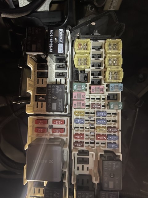
The Micro2 fuses (in the BJB) use 2.8mm Yazaki female spade terminal.
The Mini fuses in both boxes use the same (the CJB appears to use a knockoff version made by Banner).
The “Mcase” mini cartidge fuses use the mating 2.8mm male Yazaki spade terminal.
Lastly, the larger “Low Profile JCase” cartridge fuses use a 6.3mm male Yazaki spade terminal from the same product series.
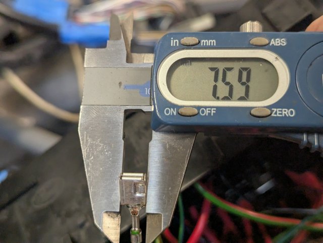
This method does have limitations. Based on the busbar sizing and length and the fuse sizing chosen by Ford, it’s probably a good idea to respect the maximum fuse size choices used by Ford, specifically 20A Micro2 and Mini, 40A MCase and 60A JCase fuses, even though there do exist larger fuses of all types. The connector terminals in question will also be limited to somewhere around 12-14 AWG wire. You might be able to stick a 10 AWG wire in the 6.3mm terminals, but its unlikely that anything larger will fit. That means anything over 20 amps will have limits on run length due to voltage drop.
Always choose an adequate wire size for the fuse amp rating you install. If you want a quick, simple guide for a circuit 20 amps or less, you can use the derated milspec wire guidelines, which are safe for continuous use at any wire length
https://www.pegasusautoracing.com/group.asp?GroupID=WIRE2
If you feel a bit more savvy and/or are installing a circuit for something greater than 20 Amps, you'll need to do a little more planning to account for wire length and the voltage drop your load can accept. Here are some 3%, 5% and 10% voltage drop charts. Even though you should be seeing >13.5V from the alternator, In some circumstances (ie at idle with a low battery) you should plan for occasionally having as low as 13-13.5V from the alternator and 12-12.5V with the ignition off. Some audio equipment especially will be unhappy with less than 11.5V at the end of the wire.
https://afe.solutions/2019/09/20/dc-wire-size-charts/
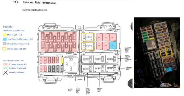
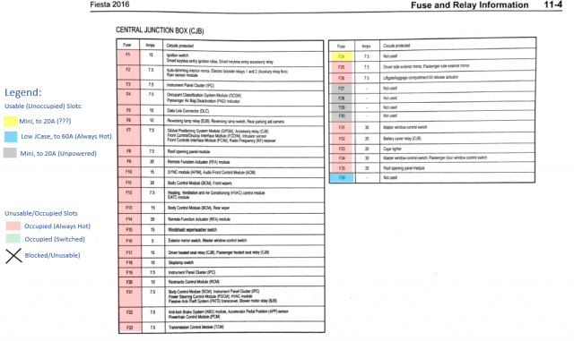
The CJB behind the glovebox is sort of accessible by unbolting it, clipping some zip ties and contorting it around, but its much harder to access and still requires wire splices (no busbars like the engine bay box), so I won’t go into it much here other than providing the circuit breakdown at the bottom.
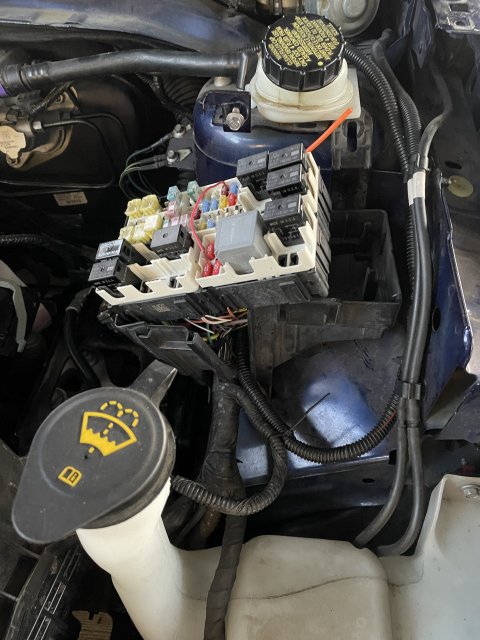
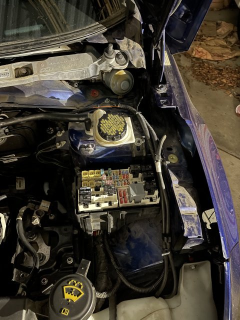
The BJB in the engine bay is much easier to get to. You'll need to get at the underside, so here's how to access it:
Tools:
T30 Torx Driver
Phillips screwdriver
Metric Socket Set
Small flathead screwdriver, or a narrow piece of metal to open plastic tabs with
Medium black zip ties
A proper open barrel crimp tool (ie, “B” shape crimper - don’t screw around with makeshift crimps or solder - not worth an electrical fire when you can at a minimum buy a decent basic IWISS crimper off Amazon for $20-40. I recommend getting a ratcheting type, which will crimp both parts of the terminal at the same time like this one:
https://www.amazon.com/IWISS-Ratcheting-Automotive-Connector-Non-Insulated/dp/B08G48C5NT/ref=sr_1_5?keywords=iwiss+ratcheting+crimping+tool&qid=1673027437&s=hi&sprefix=iwiss+ratchert,tools,133&sr=1-5
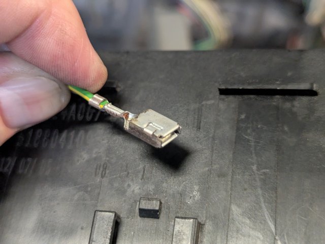
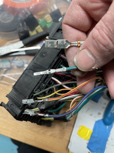
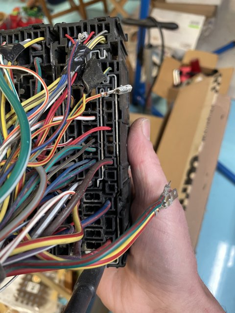
From here, you can crimp your terminals to a wire, and insert them into the appropriate slots on the back of the fusebox - doublecheck with a flashlight to make sure you have it in the desired slot. They go in pretty tight until they click, and can’t be removed unless you pull out *all* the fuses and remove the white covers. Add your fuses of choice and run your wires out with one of the two main bundles and to wherever you want them. A little black corrugated wire loom will give you a nice “OEM” look, otherwise use whatever routing you prefer. Remember to leave some extra length of wire and/or a service loop in case you need to cut the wire and redo it - you can always hide it or route it with zip ties to take up the slack.
To reassemble, reverse the steps. You’ll need new medium black zip ties to secure the main harness bundles again (the ones you clipped)
Enjoy a clean looking engine bay and a reliable electrical system! Before and after pics, you can see the new 20A and 10A Micro2 fuses I added at the bottom right.
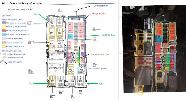
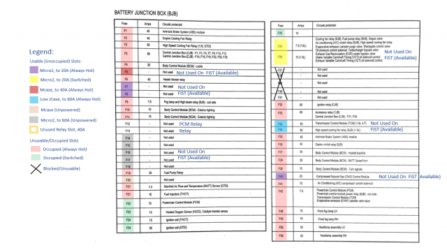
I’ve included a colored diagram below with a legend showing where the usable fuse locations in each box are as well as where the plastic retaining tabs are located. There are also some free 40A (BJB) or 20A (CJB) relay slots, but they use slightly different 4.8mm and 6.3mm spade terminals that I haven’t found the exact match to yet, but they look like a pretty standard type.
After a bit of sleuthing, and dissecting a couple of junkyard Fiesta fuseboxes, I’ve discovered how to use the unused fuse slots in the main junction boxes (and where to find new terminals) for a really clean install of those things you want to add to your car, like water/meth systems, dashcams, small subwoofers, etc. I figured it was worth putting together the information to share.
First off. Don’t do what the previous owner of my car did and jam a wire under the unfused “live” side of a fuse blade and call it a day!
With that hair raising image out of the way, it turns out there are a few unused fuse spots in both the main “battery junction box” (BJB in the electrical diagrams) in the engine bay, and a couple in the “central junction box” (CJB in the diagrams) behind the glove compartment. After dissecting fuse boxes and It turns out that both of them use Yazaki style open barrel crimp spade terminals that are available on Mouser which are listed below.
I chose to install my circuits in the engine bay BJB and run through the firewall seal for several reasons:
- It is more easily accessible.
- It has hard busbars on the rear half, which require only adding single a terminal and wire to the box to pull power, with no wire splicing or makeshift battery connections required.
- The busbars come directly off the main wire to the battery, so it is already adequate for devices up to 20, 40 or 60 amps (you might still want to upgrade the main battery cable if you intend to add high current systems like sound system upgrades though).
- The PCM relay connects to a small ignition switched busbar, which has one free switched fuse slot. The glovebox fusebox *might* have one wired to the "accessory relay", but I haven't been able to verify that that one works or not.
First off, the part numbers. (All the terminals are between 10 and 35 cents each, so get lots of extras in case you mess one up and need to redo it) .
The Micro2 fuses (in the BJB) use 2.8mm Yazaki female spade terminal.
The Mini fuses in both boxes use the same (the CJB appears to use a knockoff version made by Banner).
The “Mcase” mini cartidge fuses use the mating 2.8mm male Yazaki spade terminal.
Lastly, the larger “Low Profile JCase” cartridge fuses use a 6.3mm male Yazaki spade terminal from the same product series.
Code:
Battery Junction Box Terminals

Micro2 Fuses (to 20A):
Yazaki 2.8mm Female (19-22 AWG)    7116-4110-02
Yazaki 2.8mm Female (16-18 AWG)    7116-4111-02
Yazaki 2.8mm Female (13-15AWG)     7116-4112-02
https://www.mouser.com/c/connectors/automotive-connectors/?q=7116-411

MCase Fuses (to 40A):
Yazaki 2.8mm Male (19-22 AWG)    7114-4110-02
Yazaki 2.8mm Male (16-18 AWG)    7114-4111-02
Yazaki 2.8mm Male (13-15 AWG)    7114-4112-02
Yazaki 2.8mm Male (11-12 AWG)    7114-4113-02
    https://www.mouser.com/c/connectors/automotive-connectors/?q=7114-411

Low Profile JCase Fuses (to 60A):
Yazaki 6.3mm Male (16-20 AWG)    7114-4120-02
Yazaki 6.3mm Male (14 AWG)       7114-4121-02
Yazaki 6.3mm Male (11-13 AWG)    7114-4122-02
    https://www.mouser.com/c/connectors/automotive-connectors/?q=7114-412

Central Fuse Box Terminals

Mini Fuses (to 20A):
Banner (Yazaki) 2.8mm Female (19-22 AWG)    7116-4110-02
Banner (Yazaki) 2.8mm Female (16-18 AWG)    7116-4111-02
Banner (Yazaki) 2.8mm Female (13-15AWG)    7116-4112-02
    https://www.jameco.com/webapp/wcs/stores/servlet/CatalogSearchResultView?langId=-1&storeId=10001&catalogId=10001&subclassId=305518#/filter:ss_attr_in_stock:Yes/filter:ss_attr_manufacturer:Banner$2520Engineering
    https://www.mouser.com/c/connectors/automotive-connectors/?q=7116-411
This method does have limitations. Based on the busbar sizing and length and the fuse sizing chosen by Ford, it’s probably a good idea to respect the maximum fuse size choices used by Ford, specifically 20A Micro2 and Mini, 40A MCase and 60A JCase fuses, even though there do exist larger fuses of all types. The connector terminals in question will also be limited to somewhere around 12-14 AWG wire. You might be able to stick a 10 AWG wire in the 6.3mm terminals, but its unlikely that anything larger will fit. That means anything over 20 amps will have limits on run length due to voltage drop.
Always choose an adequate wire size for the fuse amp rating you install. If you want a quick, simple guide for a circuit 20 amps or less, you can use the derated milspec wire guidelines, which are safe for continuous use at any wire length
https://www.pegasusautoracing.com/group.asp?GroupID=WIRE2
If you feel a bit more savvy and/or are installing a circuit for something greater than 20 Amps, you'll need to do a little more planning to account for wire length and the voltage drop your load can accept. Here are some 3%, 5% and 10% voltage drop charts. Even though you should be seeing >13.5V from the alternator, In some circumstances (ie at idle with a low battery) you should plan for occasionally having as low as 13-13.5V from the alternator and 12-12.5V with the ignition off. Some audio equipment especially will be unhappy with less than 11.5V at the end of the wire.
https://afe.solutions/2019/09/20/dc-wire-size-charts/
The CJB behind the glovebox is sort of accessible by unbolting it, clipping some zip ties and contorting it around, but its much harder to access and still requires wire splices (no busbars like the engine bay box), so I won’t go into it much here other than providing the circuit breakdown at the bottom.
The BJB in the engine bay is much easier to get to. You'll need to get at the underside, so here's how to access it:
Tools:
T30 Torx Driver
Phillips screwdriver
Metric Socket Set
Small flathead screwdriver, or a narrow piece of metal to open plastic tabs with
Medium black zip ties
A proper open barrel crimp tool (ie, “B” shape crimper - don’t screw around with makeshift crimps or solder - not worth an electrical fire when you can at a minimum buy a decent basic IWISS crimper off Amazon for $20-40. I recommend getting a ratcheting type, which will crimp both parts of the terminal at the same time like this one:
https://www.amazon.com/IWISS-Ratcheting-Automotive-Connector-Non-Insulated/dp/B08G48C5NT/ref=sr_1_5?keywords=iwiss+ratcheting+crimping+tool&qid=1673027437&s=hi&sprefix=iwiss+ratchert,tools,133&sr=1-5
- Disconnect the negative battery terminal, followed by the positive terminal.
- Remove the driver’s side headlight.
- Remove the battery from the car.
- Take out the little clip on top of the plastic shield hanging off the side of the battery box. Removing the induction pipe will make this easier.
- Carefully pull the levers and demate the two connectors from the ECU which is hanging off the side of the battery box (which is not far from the exhaust manifold - who thought that was a good idea? I guess it insulates the battery a bit!)
- In the photos, I had the windshield cowl removed for some other work. This makes more space to work, but is not required.
- Remove the BJB fuse cover and locate the four little clips holding it into the lower housing. One of them is under one of the big JCase fuses which you’ll have to remove
- Carefully pop open the two “doors” on the fusebox lower cover that sit directly above the wire bundles using a small screwdriver or similar tool
- Carefully clip the two zip ties holding down the main wire bundles coming into the fusebox.
- Gently bend out the four tabs holding the fusebox to the lower cover. I ended up using a piece of metal from a windshield wiper to move the tabs and some zip ties to hold them out while removing the other tabs
- Wiggle the fusebox up out of the cover. You can remove the nuts holding the fusebox in place and slightly bend the loose part of the housing a little bit to let you tilt the fuse block toward the passenger side, giving you access to the underside of the block.
From here, you can crimp your terminals to a wire, and insert them into the appropriate slots on the back of the fusebox - doublecheck with a flashlight to make sure you have it in the desired slot. They go in pretty tight until they click, and can’t be removed unless you pull out *all* the fuses and remove the white covers. Add your fuses of choice and run your wires out with one of the two main bundles and to wherever you want them. A little black corrugated wire loom will give you a nice “OEM” look, otherwise use whatever routing you prefer. Remember to leave some extra length of wire and/or a service loop in case you need to cut the wire and redo it - you can always hide it or route it with zip ties to take up the slack.
To reassemble, reverse the steps. You’ll need new medium black zip ties to secure the main harness bundles again (the ones you clipped)
Enjoy a clean looking engine bay and a reliable electrical system! Before and after pics, you can see the new 20A and 10A Micro2 fuses I added at the bottom right.
I’ve included a colored diagram below with a legend showing where the usable fuse locations in each box are as well as where the plastic retaining tabs are located. There are also some free 40A (BJB) or 20A (CJB) relay slots, but they use slightly different 4.8mm and 6.3mm spade terminals that I haven’t found the exact match to yet, but they look like a pretty standard type.
Last edited: