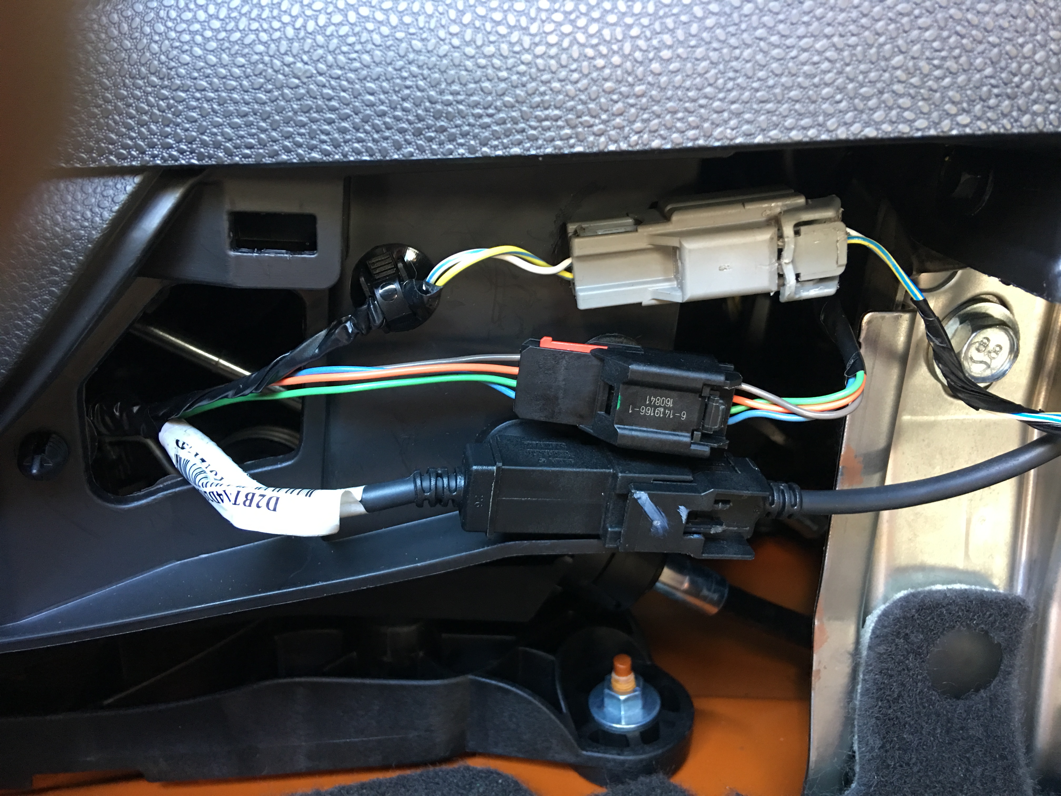
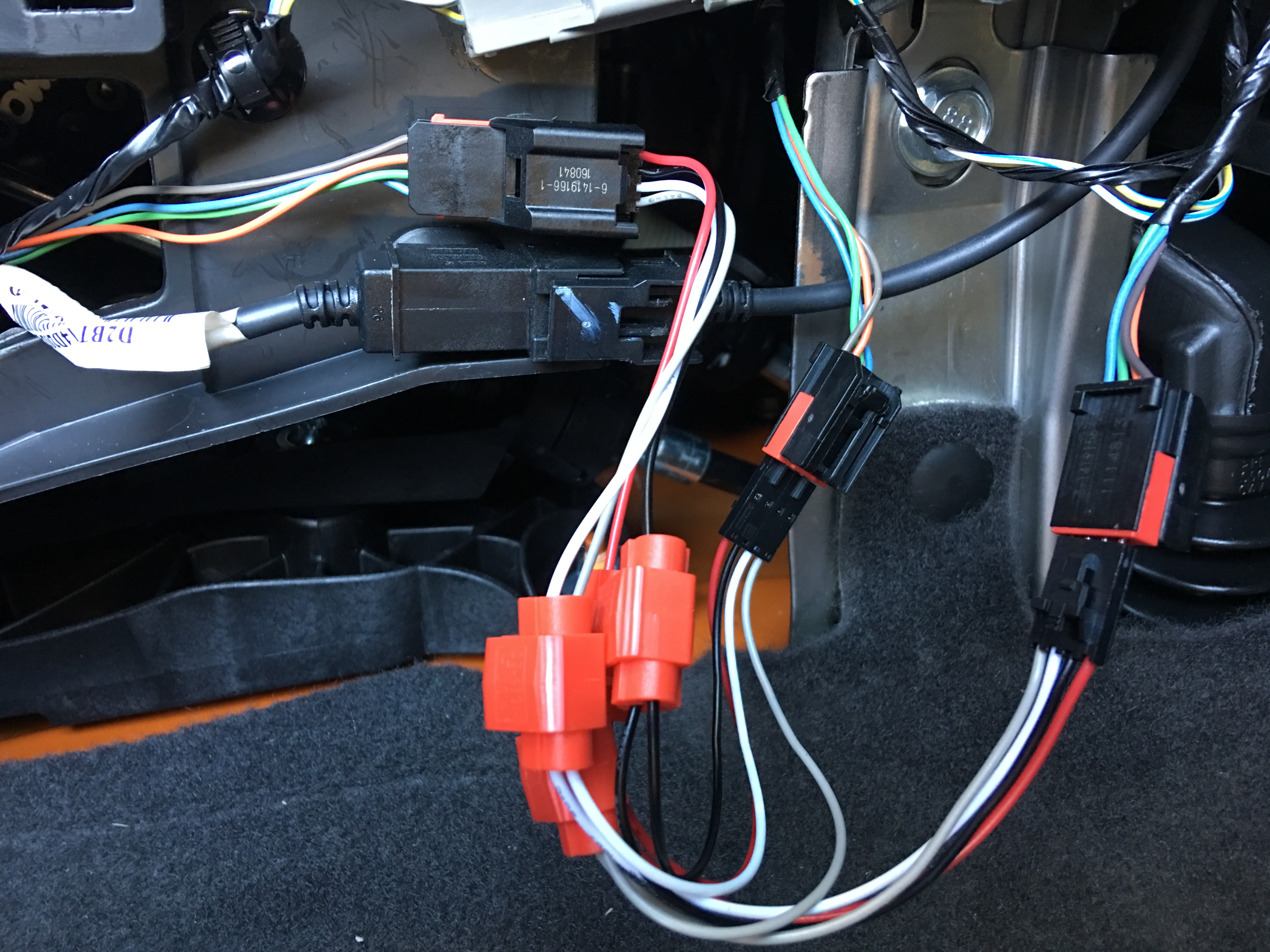
Just take 4 short pieces of solid core 18 gauge wire and strip them at both ends. Stick one of the stripped ends into the back of the OEM plug along each of the wires coming out of the back of the plug. Then stick the other stripped end of each short pieces of wire into the front of the female plug on the new harness.

-
Sign Up! To view all forums and unlock additional cool features
Welcome to the #1 Fiesta ST Forum and Fiesta ST community dedicated to Fiesta ST owners and enthusiasts. Register for an account, it's free and it's easy, so don't hesitate to join the Fiesta ST Forum today!
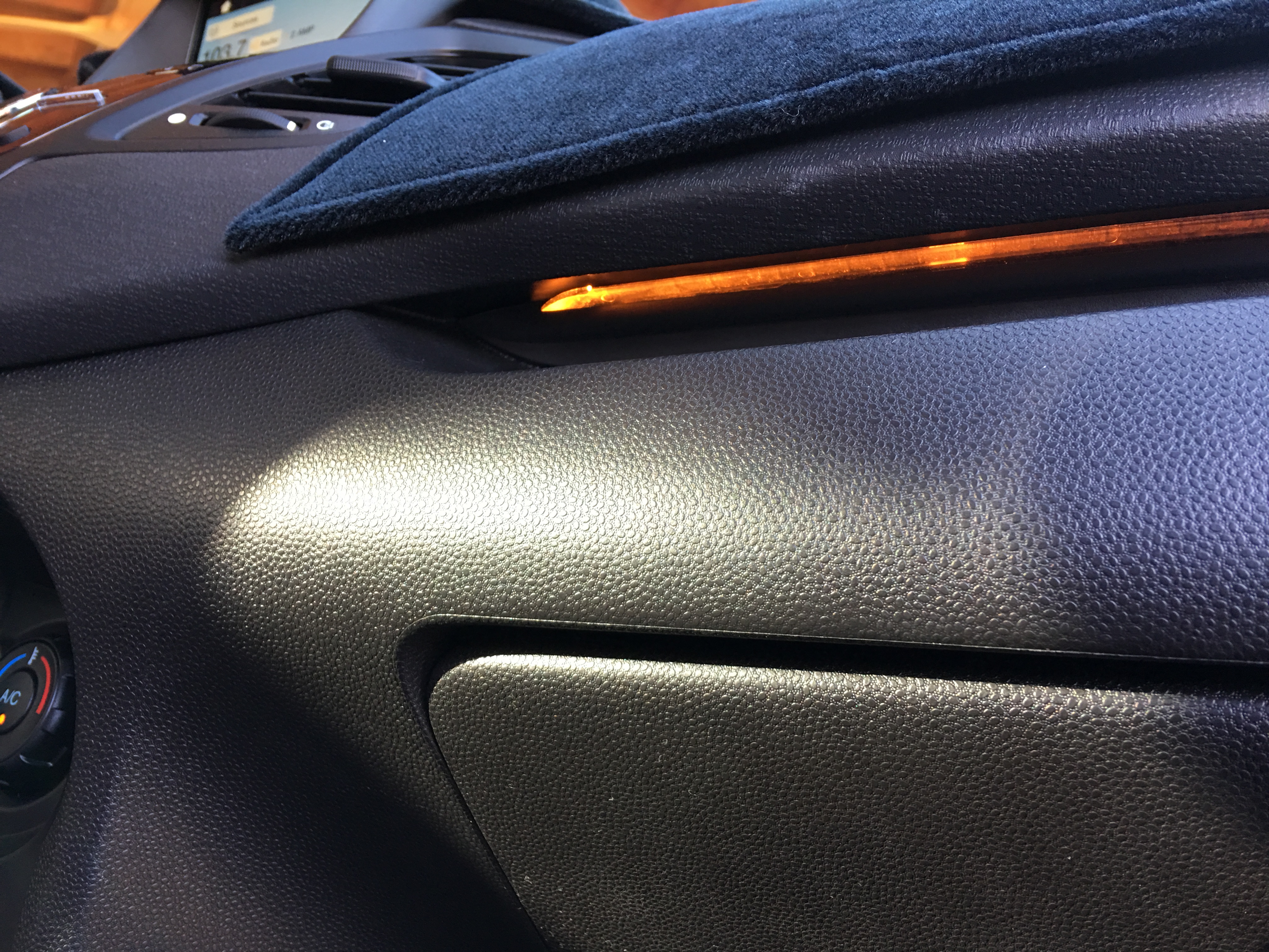
2017 Ambient Lighting No Longer Above Glove Box?!
- Thread starter Butterybunz
- Start date


Similar threads
-
-
FS 2017 Fiesta ST - Magnet Grey - 100% UNMODIFIED POWERTRAIN
- Started by Dunnerway
- Replies: 3
-
-
-
-
 FS 36k Miles 2017 Magnetic Gray FiST $11k OBO
- Started by 2017MetallicGreyFiST
- Replies: 1
-
-

-

-
