• Sign Up! To view all forums and unlock additional cool features

    Welcome to the #1 Fiesta ST Forum and Fiesta ST community dedicated to Fiesta ST owners and enthusiasts. Register for an account, it's free and it's easy, so don't hesitate to join the Fiesta ST Forum today!


Diagnosing P0326

Messages
207
Likes
144
Location
none
#1
Long story short I got a new refurbished engine after my original had a cracking experience.

Old engine was a JTJA and the new one is a JTJB. All accesories were transferred from the old engine as the new one is a short engine(block and head). It has all new OE bearings, valves, springs, gaskets, timing belt and waterpump, everything. My mechanic put it in, but ended up timing the crank wrong(it wouldn't start) and I had Ford time it properly. Starts every time no problem.

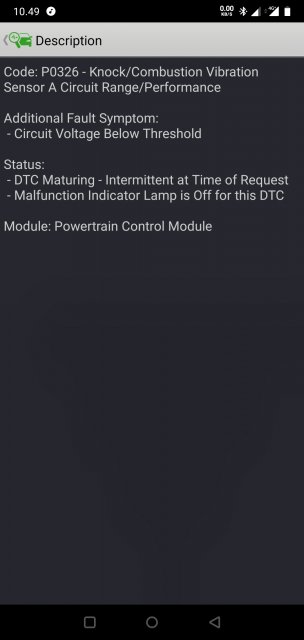
The problem now is, after around 20 minutes of driving it throws code P0326. Attached is a screendump from Forscan lite(Android app).
It puts the car in a sort of limp mode with no CEL. I can on the go remove the error and it goes out of limp mode for about 30sec and the error comes back.
It seems to only happen when it's warm but have had an instance where it would do it cold when stomping the brake in a roundabout(a truck pulled out with no real room).

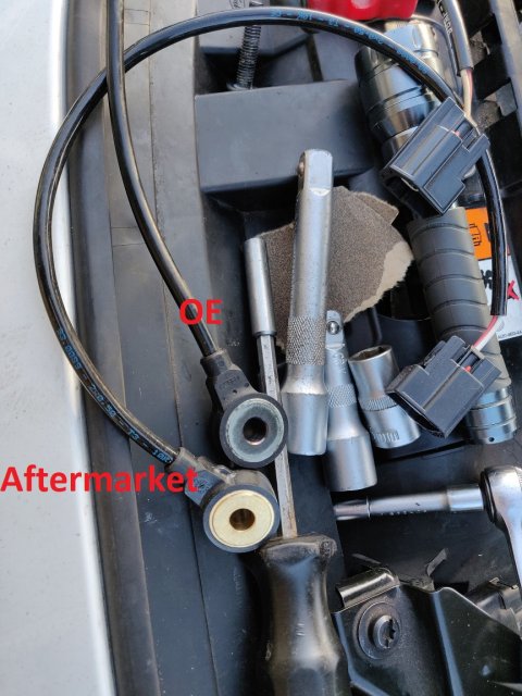
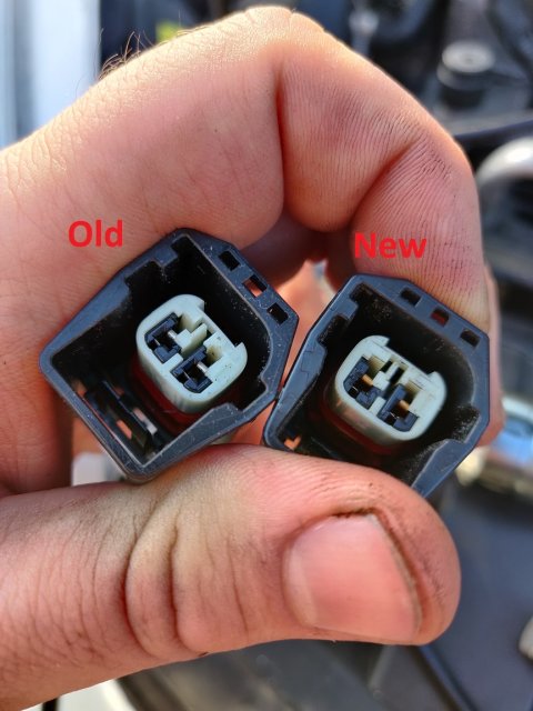
So far I've tried removing the knock sensors(both sides) and sanding the block where it contacts and cleaning both the sensor and block with brake cleaner. The problem persists.
I had it in at Ford and they said, maybe fuel pump but since they couldn't read the error(I don't know why) they couldn't diagnose it properly and referred me to a tuner. They said it fet like it didn't get enough fuel.
I checked mode:6 and it doesn't register misfires. And it doesn't feel like it misfires.
The boost doesn't want to go past 10-12psi in this limp mode.
My fuel pressure maxes out at 2200-2300psi, don't know if this is normal or not. I have a brand new HPFP and cam follower tappet ready to install.

My setup:
Block is modded with the Pumaspeed shims.
PumaSpeed X47R
Turbosmart IWG75(tune+ version)
GFB Diverter valve
Brand new Denso ITV20 spark plugs(same temp as stock)
Mishimoto OCC
R-Sport Pro 400 full size intercooler


Attachments

TyphoonFiST

9000 Post Club
Premium Account
Messages
11,516
Likes
8,009
Location
Rich-fizzield
#2
Silly question....is the sensor plugged in? How does the connector look? Is it corroded or have any nicked wiring? Is there any fuses blown?

Sent from my SM-N950U1 using Tapatalk


TyphoonFiST

9000 Post Club
Premium Account
Messages
11,516
Likes
8,009
Location
Rich-fizzield
#4
I think you should be also Running a step colder than stock plugs either a 6510 NGKs or ITV22 I do believe with a setup like that.


Rocketst

1000 Post Club
Messages
1,272
Likes
842
Location
Chesapeake, VA, USA
#5
What I'm trying to say is, if the shims were installed and there was even a small margin of play you could be getting a vibration from the shims which would register as knock to the car. But check your wires. There's been so many times I've accidently put a harness too close movable parts. I had an o2 sensor on a prelude get ripped off by the front axle one time and it killed the car. Couldn't start it and had no idea what was wrong.

Sent from my moto z4 using Tapatalk


OP
daloonie
Messages
207
Likes
144
Location
none
Thread Starter #6
Sensors are plugged in, no nicked wires to speak of, but I will be checking the routing. Connectors looks in mint condition. They are routed behind the throttle body so hard to see without removing throttle body and intake tube. Both should be located correctly according to the manual.

Shims were installed by my mechanic, I trust he did check that, but will be checking with him.

I have run ITV20's before with no problems on the old engine, but I'll order som ITV22's just to be sure.


Messages
213
Likes
156
Location
WICHITA
#7
see what the ohm specification is for the sensor and test it at the pigtail. have whoever is working on it compare the readings to the other knock sensor. I want to say sensor A is for cyl 1 and 2 and sensor B is for cyl 3 and 4.

Sent from my SM-G973U using Tapatalk


OP
daloonie
Messages
207
Likes
144
Location
none
Thread Starter #9
Yes indeed bank a is cylinder 1 & 2. I think I have solved the issue. I got a new sensor since they are pretty cheap, not oe though. They go for around $30 so it was a no brainer. Only problem was availability.

Today I changed the bank a sensor and went for a 1 hour drive and no problems at all.
Now the real test awaits. Daily driving it to and from work, hoping it all goes well.

I have pictures if anyone has to do a similar job I'll post some tips and hints for some of the job that will make it ten times easier.


OP
daloonie
Messages
207
Likes
144
Location
none
Thread Starter #10
First off this is only for sensor A but for sensor B I would probably do all of this anyways to be able to route the pigtail.

You need the following to do this simple job:
Torx T25 bit
Screwdriver with bits attachment or a T25.
Small ratchet(not necessary but very convenient). I used a 4" long 1/4" ratchet with a bits attachment. And a 2" extender
7mm socket
10mm socket with a 3 to 5" extender. I would recommend a medium sized 1/2"
13mm socket
Oil filter wrench

It's very hard to see the knock sensor with the intake on. But taking the intake off is not necessary to change the sensor. You can spot the sensor right through here:
peephole.jpg

To get to it I recommend taking off the cold side boost pipe. From topside it's very easy to get the top hose clamp off(2) with a 7mm socket. Pull off the vacuum hose(1) first and pull it aside. It's a push clip so squeeze from top and bottom and pull it off.
topside.jpg
Take the coolant hose(3) and move it towards the top of the engine as well to give better clearance later.

From the bottom release the hose clamp to the cold side pipe. The unscrew the 13mm nut that's holding it in place. Pull it off the holder and downwards, but be careful there's still a vacuum line and a temperature sensor(I believe that is what it is). The vacuum hose has a plastic clip that's easy to pop off from the bottom and then just pull it off. Same clip type as on the intake The temperature sensor is fastened with a 7mm socket screw.

Now you can pull it out fully.

Now the trick to get the throttle body out is all about access. I removed the oil filter, which helped a great deal. I lost about 10cl of oil as it is way easier to manouver it out without spilling when the cold side pipe is out of the way. Then from the bottom you can get the 2 T25 screws closest to the block. These are pretty long screws so be patient.
From the top I used a small ratchet with a small extender and a torx bit. That was ten times easier on the outer screws than from the bottom, but almost impossible on the 2 inside screws.
The throttle body has a click on connector. Remove it and you're ready to get to the knock sensor with much needed space. Fair warning even like this I had to put in half my arm into the engine crevasse to get it out and in. Once the screw is loose use your hand to fully remove it to not loose the screw.

To get to the sensor now you have to be use a ratchet with a 10mm socket and extender on the socket. Using the little peephole you can maneouvre it into place and easily get it out. The pigtail is lodged inbetween the intake but can be pulled out without destroying it. Just pull it straight towards the front carefully.

To install just reverse it, it's not hard and for a 10 thumb numpty like me it was possible ;)

I've attached a picture of the OE part number.


Attachments

OP
daloonie
Messages
207
Likes
144
Location
none
Thread Starter #11
For reference I replaced mine and this is what I found.
knockvknock.jpg pigtail.jpg

And my clip it attached to was broken, so I used a piece of tape to make it friction fit.

So far no errors and runs great.


Similar threads


Top