
After seeing posts like the one below for an automatic circuit/module that used to be available that will automatically “press” the ESC button for me every time I start the car, I decided to take matters into my own hands and cook something up.
Credit to @JDG : https://www.fiestastforum.com/threads/plug-and-play-traction-control-off-module.18531/
Since I can do basic electronics, and don’t have much experience with stuff like microcontrollers, I had to get creative. I’ve decided to share how I did it, because I think anyone who understands basic wire harnesses and can crimp a connector can probably make this themselves.
First off, The ESC button is a “momentary contact” button. It works by taking a signal that’s normally floating at a positive voltage from the ABS Module, and “pulling it down” by connecting it to ground whenever the button is held down. That’s literally all the button itself does - everything else happens inside the ABS module programming.
Basically you need to make a few things:
Tools:
- Philips Screwdriver
- Miniature File (Triangle or Square file)
- Open Barrel “B” Crimper (I use this IWISS crimper - it is half decent and affordable for hobby use): https://www.amazon.com/IWISS-Ratcheting-Crimping-Tool-Non-Insulated/dp/B08DRCRRCQ/ref=sr_1_5?keywords=iwiss+open+barrel+crimping+tool&qid=1673718158&s=hi&sprefix=iwiss+open+barrel+crimp,tools,188&sr=1-5 )
Parts:
- 1x to 3x TE “GET 0.64” Female 1x6 connector (1456985-3): https://www.mouser.com/ProductDetail/571-1456985-3
- 1x to 3x TE “GET 0.64” Male 1x8 connector (9-1419166-0): https://www.mouser.com/ProductDetail/571-9-1419166-0
- 100x Female terminals (1719958-1): https://www.mouser.com/ProductDetail/571-1719958-1-CT
- 100x Male terminals: (1438299-4): https://www.mouser.com/ProductDetail/571-1438299-4-CT
(pins only come in strips of 100. Buy an extra connector or two in case you make a mistake, they are cheap):
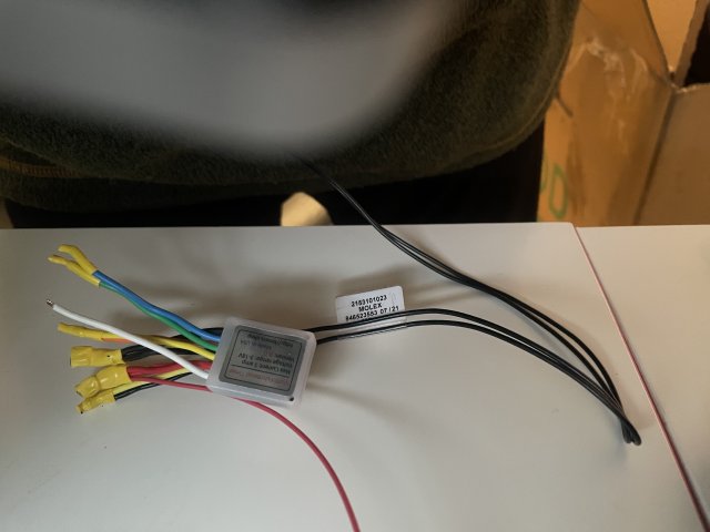
- 1x "Timers.shop" Multi-Function Time Delay Relay: https://timers.shop/Multi-Functional-3V-18V-Time-Delay-Relay-Timer--5-amp-V8_p_77.html
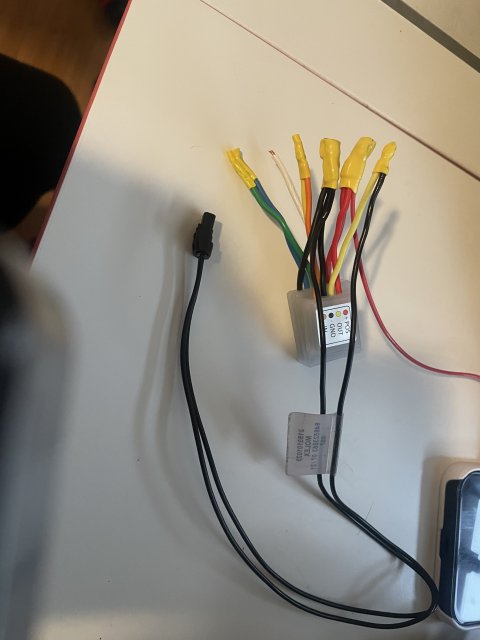
- 1x "Timers.shop" Positive to Sink Adapter: https://timers.shop/Sink-Adapter--Positive-To-Sink_p_32.html
- 18 or 20 awg wire (recommend at least 2-3 colors, but one will do)
- Extra generic connectors if you want to split the harness in multiple pieces to make it easier to install.
- Solder and Heatshrink to lash splice, or some type of crimp splice or quick wire connectors for 2-4 wires
- Zip ties
At the most basic, the min total cost is about $50 for the timer relay and TE connector parts, not including tools. If anyone is interested, I have a lot of extra pins lying around now!:
Step 1: Make the jumper harness.
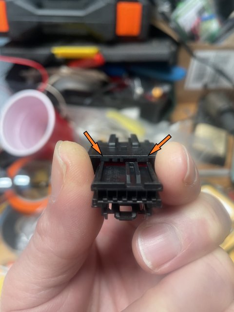
Since a 6-pin “male pin” connector apparently doesn’t exist, the 8-pin version with similar keying can be modified to accept the female 6 pin connector. The 8 pin has extra material that blocks the 6 pin connector from mating, so simply file these back until the 6 pin fits in the middle, mating with pins 2-7. (Ignoring pins 1 and 8)
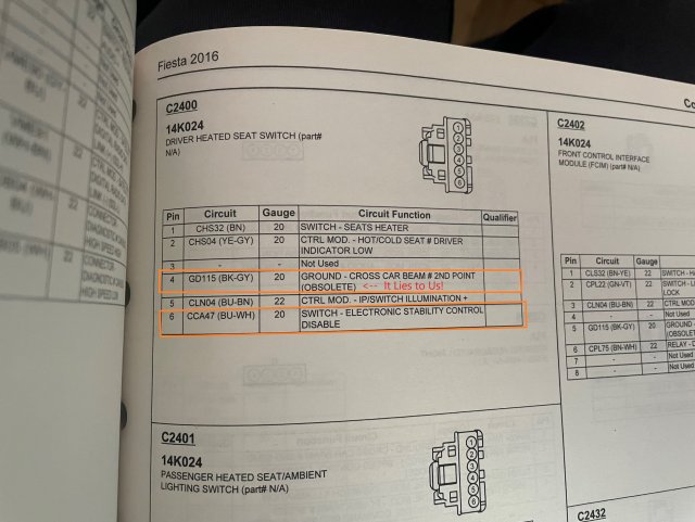
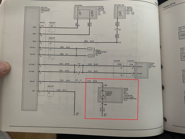
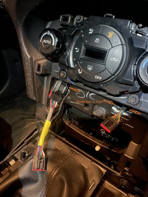
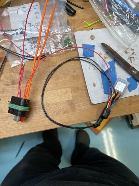
If you open the climate control panel, you’ll find that the ESC/Driver’s seat heater button is connected via a black and red 6 pin connector. Pins 4 (GND) and 6 (ESC Button Signal) on this connector are the one’s we’re interested in. In the Fiesta wiring diagrams, the connector is tagged C2400
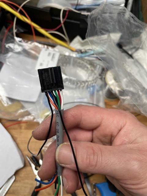
We’ll need to connect all 6 pins. For the relay timer, You can either splice a pair of long wires into the jumper wires or double up on the pin 4 and 6 crimps with a pair of longer wires that will route to the glovebox area. Keep track of which is which and make the leads at least ~3ft long just so you have plenty to work with. (I used a pair of prewired connector pigtails I had lying around)
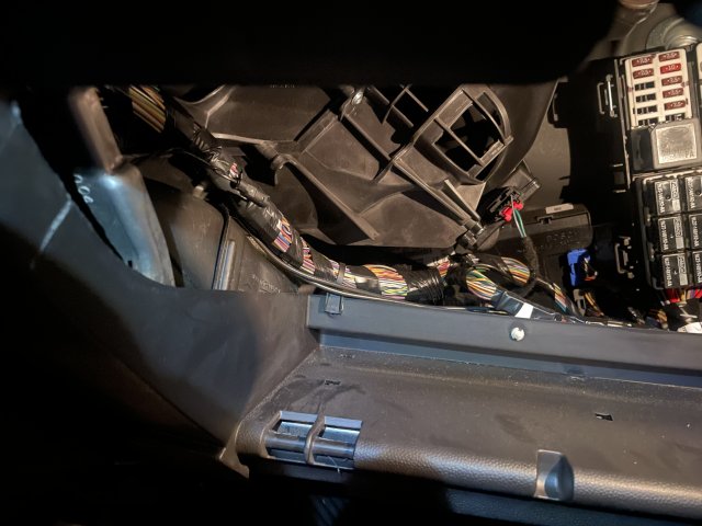
Once you have the jumper harness, you can pull the glovebox, the passenger footwell trim, and then pull the trim starting at the shifter and working up to the climate control panel. The original module thread linked at the top has a video that explains it well.
After you have it open, demate the left side ESC/Heated seat connector (should be the same plug regardless of whether you have heated seats), and plug the 8-pin connector into the factory harness.
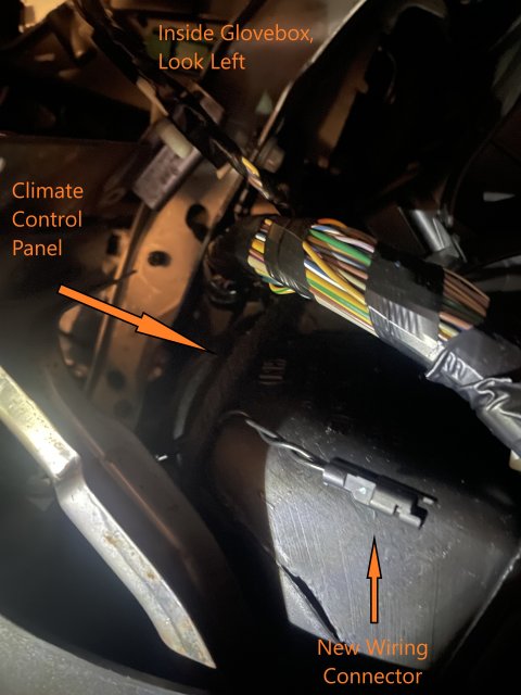
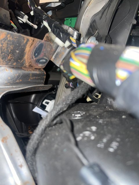
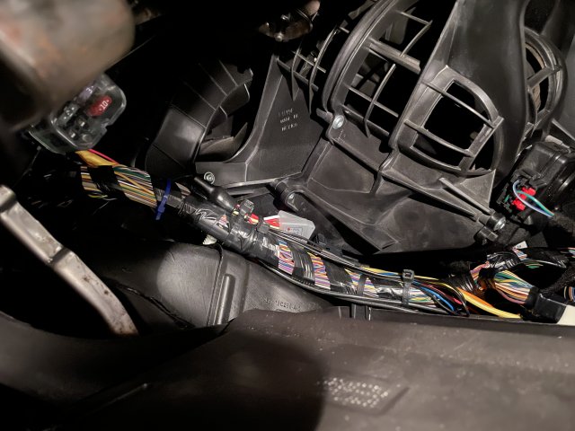
Fish the two spliced wires (ESC and GND) over towards the glovebox area. You can route a longer wire underneath like the original directions, or do as I did and fish a shorter wire horizontally, past the passenger heated seat button, and then directly behind the dash into the area behind the glovebox. Just be careful not to run the wire along the existing dash harness, and not over some of the sharp steel edges on the dash structural frame.
At this point you can plug in to the ESC button. If you have an ohmmeter or continuity checker, measure resistance from the GND wire to anywhere on the car body, then measure between the GND and ESC wires while holding the ESC button down. Both tests should register a connection. Once you are confident, you can close up the climate control panel - the rest of the work is all behind the glovebox.
Step 2: Program the time delay relay.
Follow the instructions on the Timers.shop website to configure the timer. There’s a manual and instructional videos. Note, you could easily use a different timer option
https://timers.shop/Multi-Functional-3V-18V-Time-Delay-Relay-Timer--5-amp-V8_p_77.html
For this application, I’ve chosen to set it to Mode 7 “Delayed Interval Single Cycle”. When the timer gets power from the ignition switched circuit, it will wait until time “t1”, then give a single pulse of time “t2”, then shut off. Set “t1” to about 30 seconds after the ignition comes on. For time “t2” it depends on what behavior you want.
For “sport mode”, I’ve found an ideal time is about 100-120 milliseconds (set it to 3 or 4 “1/30ths” of a second). If you set it too long (like 1 second), the ABS module will think you’re trying to push and hold for ESC-off mode, start the progress-bar, and then drop out without changing modes.
For full ESC-off, a nice generous 6 seconds should work, but I haven’t tested since I opted for “sport mode”. If you try it, post on how it went
Step 3: Wire up the timer and “sink adapter” and install
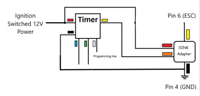
The timer relay we are using has one shortcoming - it gets really unhappy if you short the output directly to ground - it prefers to output an on-off voltage, not run power to ground. Fortunately, they make a “sink adapter” which is basically a separate electronic relay. You could probably also use a mechanical relay if you set the timing right. I confirmed with the maker/seller that the sink adapter doesn’t care what voltage is input on the “load” line - it doesn’t have to match the red power input wire. Here’s a helpful diagram that I’ve modified to illustrate how it’s wired up - each junction needs a solder splice or crimp. Basically, reds all to power, blacks all to the pin 4 wire (which is our chassis ground). Yellow timer output to orange sink input. Yellow sink input to pin 6 ESC wire. Ignore (and cap or tape) the blue/green wires. Consider leaving the white wire accessible until after you’ve tested out the car in case you need to reconfigure the timer. I’ve split my harness into two pieces with a two-pin connector to make the install simpler so I can just work on a bench and then plug things in and not mess with crimps or soldering inside the dash
Leave a long tail on the red power wire after splicing to connect to ignition switched 12V power.
From here you can either connect to a fuse tap in the fuse box behind the glovebox, or add a circuit to the fusebox. Just make sure the connection is switched with the ignition and not “always hot”
https://www.fiestastforum.com/threa...erminal-part-numbers-no-more-fuse-taps.30228/
In the pictures I’ve included, you’ll see a small 4 slot fusebox connected to the red wire, and a bunch of extra wires from it. I’ve taken power from the battery fuse box in the engine bay as I’ve shown in my other thread and in addition to this circuit, it also runs switched and always hot power to a small subwoofer, so you can ignore the extra wires.
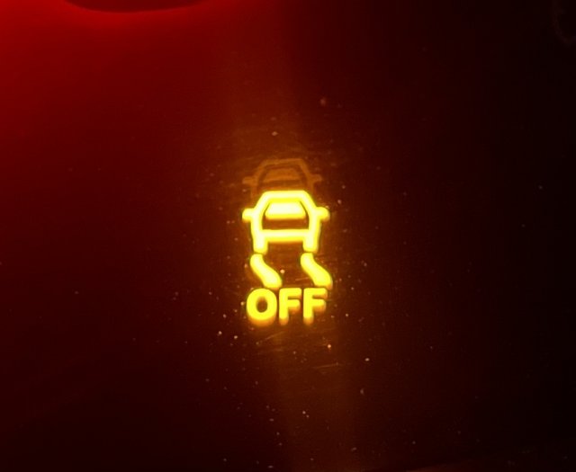
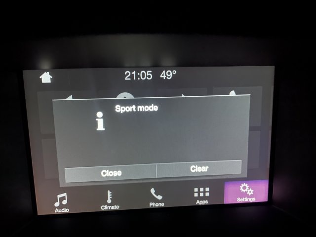
Once you’ve hooked up everything, turn the ignition on and wait until your chosen mode shows up on the screen and the ESC-off light comes on the dash. Once you are happy, secure the module to the dash harness with zip ties and close everything up!
Before/After:
30 Seconds Later!
Credit to @JDG : https://www.fiestastforum.com/threads/plug-and-play-traction-control-off-module.18531/
Since I can do basic electronics, and don’t have much experience with stuff like microcontrollers, I had to get creative. I’ve decided to share how I did it, because I think anyone who understands basic wire harnesses and can crimp a connector can probably make this themselves.
First off, The ESC button is a “momentary contact” button. It works by taking a signal that’s normally floating at a positive voltage from the ABS Module, and “pulling it down” by connecting it to ground whenever the button is held down. That’s literally all the button itself does - everything else happens inside the ABS module programming.
Basically you need to make a few things:
- A 6 wire jumper harness so you can splice into the wires without hacking up the factory harness
- Some way to simulate a momentary keypress with set duration, which I’ll show later is essentially a timer relay you can purchase for $30-50 (depending if you keep the programmer, or return it as a “rental”). There are probably other ways to do this with different hardware.
- An ignition switched power source, either a fuse tap or add a circuit to a fusebox in some other way like the writeup I’ve posted below
Tools:
- Philips Screwdriver
- Miniature File (Triangle or Square file)
- Open Barrel “B” Crimper (I use this IWISS crimper - it is half decent and affordable for hobby use): https://www.amazon.com/IWISS-Ratcheting-Crimping-Tool-Non-Insulated/dp/B08DRCRRCQ/ref=sr_1_5?keywords=iwiss+open+barrel+crimping+tool&qid=1673718158&s=hi&sprefix=iwiss+open+barrel+crimp,tools,188&sr=1-5 )
Parts:
- 1x to 3x TE “GET 0.64” Female 1x6 connector (1456985-3): https://www.mouser.com/ProductDetail/571-1456985-3
- 1x to 3x TE “GET 0.64” Male 1x8 connector (9-1419166-0): https://www.mouser.com/ProductDetail/571-9-1419166-0
- 100x Female terminals (1719958-1): https://www.mouser.com/ProductDetail/571-1719958-1-CT
- 100x Male terminals: (1438299-4): https://www.mouser.com/ProductDetail/571-1438299-4-CT
(pins only come in strips of 100. Buy an extra connector or two in case you make a mistake, they are cheap):
- 1x "Timers.shop" Multi-Function Time Delay Relay: https://timers.shop/Multi-Functional-3V-18V-Time-Delay-Relay-Timer--5-amp-V8_p_77.html
- 1x "Timers.shop" Positive to Sink Adapter: https://timers.shop/Sink-Adapter--Positive-To-Sink_p_32.html
- 18 or 20 awg wire (recommend at least 2-3 colors, but one will do)
- Extra generic connectors if you want to split the harness in multiple pieces to make it easier to install.
- Solder and Heatshrink to lash splice, or some type of crimp splice or quick wire connectors for 2-4 wires
- Zip ties
At the most basic, the min total cost is about $50 for the timer relay and TE connector parts, not including tools. If anyone is interested, I have a lot of extra pins lying around now!:
Step 1: Make the jumper harness.
Since a 6-pin “male pin” connector apparently doesn’t exist, the 8-pin version with similar keying can be modified to accept the female 6 pin connector. The 8 pin has extra material that blocks the 6 pin connector from mating, so simply file these back until the 6 pin fits in the middle, mating with pins 2-7. (Ignoring pins 1 and 8)
If you open the climate control panel, you’ll find that the ESC/Driver’s seat heater button is connected via a black and red 6 pin connector. Pins 4 (GND) and 6 (ESC Button Signal) on this connector are the one’s we’re interested in. In the Fiesta wiring diagrams, the connector is tagged C2400
We’ll need to connect all 6 pins. For the relay timer, You can either splice a pair of long wires into the jumper wires or double up on the pin 4 and 6 crimps with a pair of longer wires that will route to the glovebox area. Keep track of which is which and make the leads at least ~3ft long just so you have plenty to work with. (I used a pair of prewired connector pigtails I had lying around)
Once you have the jumper harness, you can pull the glovebox, the passenger footwell trim, and then pull the trim starting at the shifter and working up to the climate control panel. The original module thread linked at the top has a video that explains it well.
After you have it open, demate the left side ESC/Heated seat connector (should be the same plug regardless of whether you have heated seats), and plug the 8-pin connector into the factory harness.
Fish the two spliced wires (ESC and GND) over towards the glovebox area. You can route a longer wire underneath like the original directions, or do as I did and fish a shorter wire horizontally, past the passenger heated seat button, and then directly behind the dash into the area behind the glovebox. Just be careful not to run the wire along the existing dash harness, and not over some of the sharp steel edges on the dash structural frame.
At this point you can plug in to the ESC button. If you have an ohmmeter or continuity checker, measure resistance from the GND wire to anywhere on the car body, then measure between the GND and ESC wires while holding the ESC button down. Both tests should register a connection. Once you are confident, you can close up the climate control panel - the rest of the work is all behind the glovebox.
Step 2: Program the time delay relay.
Follow the instructions on the Timers.shop website to configure the timer. There’s a manual and instructional videos. Note, you could easily use a different timer option
https://timers.shop/Multi-Functional-3V-18V-Time-Delay-Relay-Timer--5-amp-V8_p_77.html
For this application, I’ve chosen to set it to Mode 7 “Delayed Interval Single Cycle”. When the timer gets power from the ignition switched circuit, it will wait until time “t1”, then give a single pulse of time “t2”, then shut off. Set “t1” to about 30 seconds after the ignition comes on. For time “t2” it depends on what behavior you want.
For “sport mode”, I’ve found an ideal time is about 100-120 milliseconds (set it to 3 or 4 “1/30ths” of a second). If you set it too long (like 1 second), the ABS module will think you’re trying to push and hold for ESC-off mode, start the progress-bar, and then drop out without changing modes.
For full ESC-off, a nice generous 6 seconds should work, but I haven’t tested since I opted for “sport mode”. If you try it, post on how it went
Step 3: Wire up the timer and “sink adapter” and install
The timer relay we are using has one shortcoming - it gets really unhappy if you short the output directly to ground - it prefers to output an on-off voltage, not run power to ground. Fortunately, they make a “sink adapter” which is basically a separate electronic relay. You could probably also use a mechanical relay if you set the timing right. I confirmed with the maker/seller that the sink adapter doesn’t care what voltage is input on the “load” line - it doesn’t have to match the red power input wire. Here’s a helpful diagram that I’ve modified to illustrate how it’s wired up - each junction needs a solder splice or crimp. Basically, reds all to power, blacks all to the pin 4 wire (which is our chassis ground). Yellow timer output to orange sink input. Yellow sink input to pin 6 ESC wire. Ignore (and cap or tape) the blue/green wires. Consider leaving the white wire accessible until after you’ve tested out the car in case you need to reconfigure the timer. I’ve split my harness into two pieces with a two-pin connector to make the install simpler so I can just work on a bench and then plug things in and not mess with crimps or soldering inside the dash
Leave a long tail on the red power wire after splicing to connect to ignition switched 12V power.
From here you can either connect to a fuse tap in the fuse box behind the glovebox, or add a circuit to the fusebox. Just make sure the connection is switched with the ignition and not “always hot”
https://www.fiestastforum.com/threa...erminal-part-numbers-no-more-fuse-taps.30228/
In the pictures I’ve included, you’ll see a small 4 slot fusebox connected to the red wire, and a bunch of extra wires from it. I’ve taken power from the battery fuse box in the engine bay as I’ve shown in my other thread and in addition to this circuit, it also runs switched and always hot power to a small subwoofer, so you can ignore the extra wires.
Once you’ve hooked up everything, turn the ignition on and wait until your chosen mode shows up on the screen and the ESC-off light comes on the dash. Once you are happy, secure the module to the dash harness with zip ties and close everything up!
Before/After:
30 Seconds Later!
Last edited: