NUTSHELL: The USB Port Hub Module receives 12v power from the Sync Radio, whenever the radio turns on. This can be tapped and used as a remote turn-on for you amplifier. I am also taking the extra step, of having both 12v Outlets de/activate with the Amp. There will be a switch that reverts both outlets to default behavior.
My 2016 model has two 12v outlets and a Sync 3 radio. The front outlet (running a volt-meter) is hot at al times. The rear outlet (running my GPS) turns off with an approximate ten minute delay. Both normally remain on as I walk away from the car. This modification is intended to stop this behavior; with an option to revert to default behavior with the simple flick of a switch.
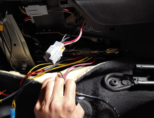
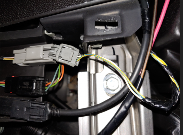
* In the passenger footwell, there is a side cover for the center console. Remove this side cover to expose the wire harness for the USB Port Hub Module. The Yellow/Blue wire is positive. The Pink/Blue (white/black) wire is ground. Tap both wires and run to your relay coil. Recommend that you tap the center console side of the harness and not the radio side of the harness. (Ground wire changes color through harness.)
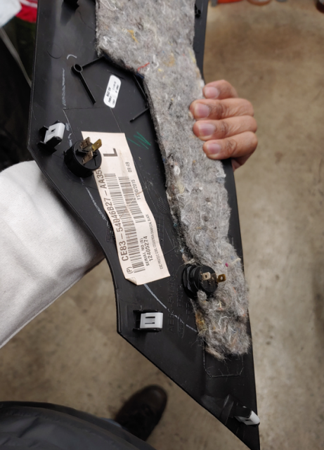
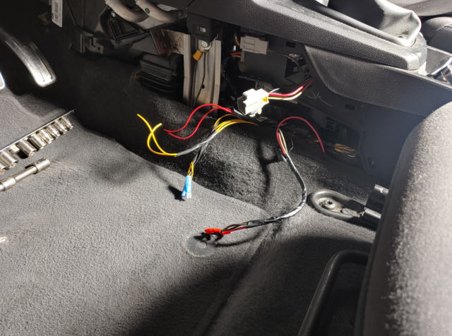
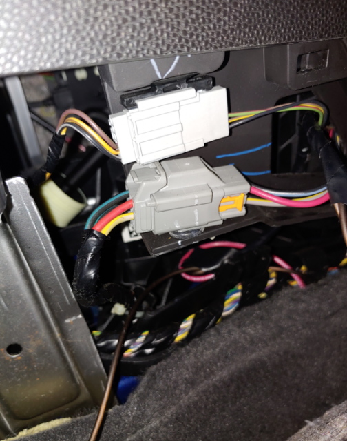
* In the driver footwell there is a side cover for the center console. Remove this side cover and expose the wire harness for the 12v Outlets. The Red wire is the front outlet. The Grey/Yellow wire is the rear outlet. Recommend you cut the center-console side of the harness and not the vehicle side of the harness.
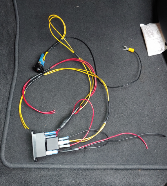
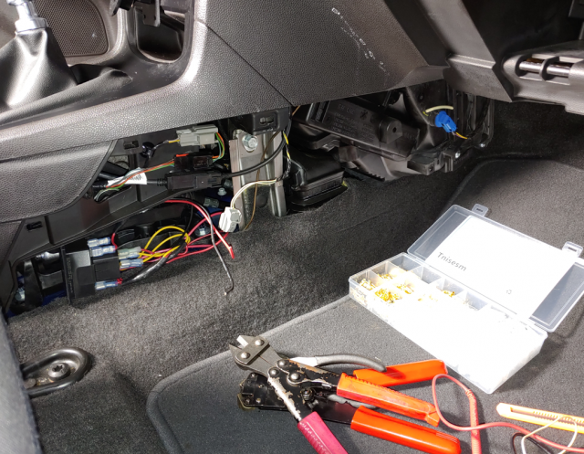
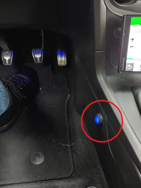
* There is no room behind the driver footwell center console side panel. Assemble everything outside the vehicle, then install into the passenger footwell side. Run your wires underneath the shifter frame. Make sure there is clearance behind switch(es) installed to the driver side panel. Make sure none of the wires interfere with shifter movement. Make sure the wires are secure, won't experience chaffing from the normal vibrations. Make sure connections won't corrode under high-humidity conditions. (dielectric grease helps)
There are four possible setups.
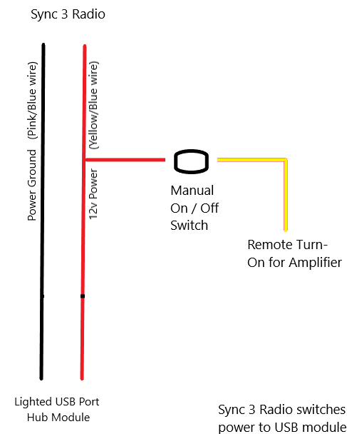
This is just a simple tap to positive wire for remote turn-on.
The amp only activates when the radio is active.
The radio needs a little head-start to load content, so may conditionally activate the USB ports when you open a door.
The switch (see "switches and relays" heading) is optional; allows you to turn off the amp with the radio still running.
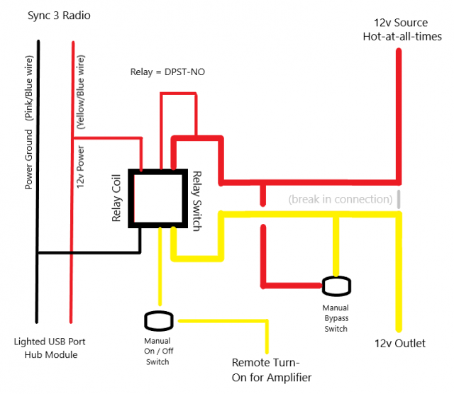
This diagram setup, adds the front outlet; so it is switched on/off similar to the amp.
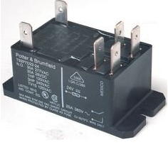
It uses a SPST-NO relay; available at any auto parts store.
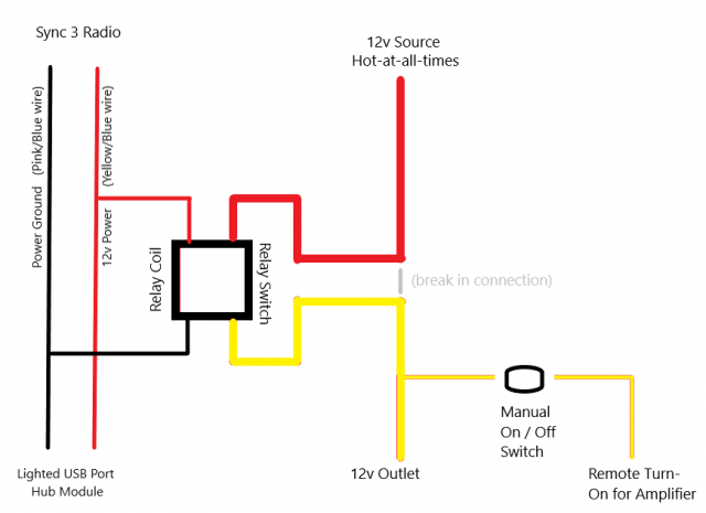
This diagram uses a DPST-NO relay, with a second switch. The second switch allows you to revert the 12v Outlet to original behavior; and not activate the amp in the process.
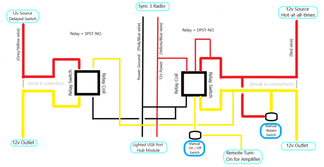
This setup uses two relays and two switches. It switches both 12v Outlets on/off with the radio. One switch controls the amp, the other reverts both 12v outlets back to default behavior. One relay is SPST-NO and the other is DPST-NO.
Switches and Relays:
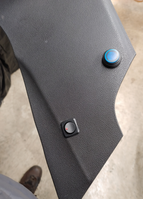
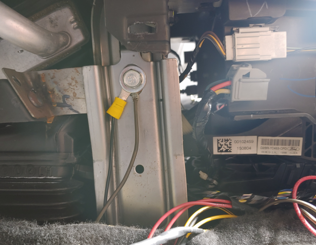
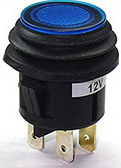
Some lighted switches require a third connection to ground. There's a convenient spot for ground in the driver footwell; a bolt behind that center console panel. Make sure your connections are clean.
https://www.amazon.com/gp/product/B00S8R2DC0/
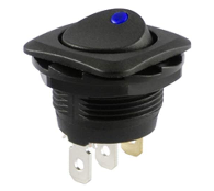
I used a simple rocker switch for the 12v Outlet switch.
https://www.amazon.com/gp/product/B008UTX208/
SPST-NO relays are available at any auto parts store.
DPST-NO relays may be found online at https://www.digikey.com/
If you find a local spot for those relays, let us know.
My 2016 model has two 12v outlets and a Sync 3 radio. The front outlet (running a volt-meter) is hot at al times. The rear outlet (running my GPS) turns off with an approximate ten minute delay. Both normally remain on as I walk away from the car. This modification is intended to stop this behavior; with an option to revert to default behavior with the simple flick of a switch.
* In the passenger footwell, there is a side cover for the center console. Remove this side cover to expose the wire harness for the USB Port Hub Module. The Yellow/Blue wire is positive. The Pink/Blue (white/black) wire is ground. Tap both wires and run to your relay coil. Recommend that you tap the center console side of the harness and not the radio side of the harness. (Ground wire changes color through harness.)
* In the driver footwell there is a side cover for the center console. Remove this side cover and expose the wire harness for the 12v Outlets. The Red wire is the front outlet. The Grey/Yellow wire is the rear outlet. Recommend you cut the center-console side of the harness and not the vehicle side of the harness.
* There is no room behind the driver footwell center console side panel. Assemble everything outside the vehicle, then install into the passenger footwell side. Run your wires underneath the shifter frame. Make sure there is clearance behind switch(es) installed to the driver side panel. Make sure none of the wires interfere with shifter movement. Make sure the wires are secure, won't experience chaffing from the normal vibrations. Make sure connections won't corrode under high-humidity conditions. (dielectric grease helps)
There are four possible setups.
This is just a simple tap to positive wire for remote turn-on.
The amp only activates when the radio is active.
The radio needs a little head-start to load content, so may conditionally activate the USB ports when you open a door.
The switch (see "switches and relays" heading) is optional; allows you to turn off the amp with the radio still running.
This diagram setup, adds the front outlet; so it is switched on/off similar to the amp.
It uses a SPST-NO relay; available at any auto parts store.
This diagram uses a DPST-NO relay, with a second switch. The second switch allows you to revert the 12v Outlet to original behavior; and not activate the amp in the process.
This setup uses two relays and two switches. It switches both 12v Outlets on/off with the radio. One switch controls the amp, the other reverts both 12v outlets back to default behavior. One relay is SPST-NO and the other is DPST-NO.
Switches and Relays:
Some lighted switches require a third connection to ground. There's a convenient spot for ground in the driver footwell; a bolt behind that center console panel. Make sure your connections are clean.
https://www.amazon.com/gp/product/B00S8R2DC0/
I used a simple rocker switch for the 12v Outlet switch.
https://www.amazon.com/gp/product/B008UTX208/
SPST-NO relays are available at any auto parts store.
DPST-NO relays may be found online at https://www.digikey.com/
If you find a local spot for those relays, let us know.
Last edited: