Did you remember to replace the crash sensors for the airbag? They might be one time use only. the brake one might be related to the abs system faults. At least thats how it was on my now 13 year old focus. Id check the iat sensor on the intake and look to see if any of the intake manifold or airbox or plumbing for it got cracked in the crash. ( this happened with my mom's 08 focus when she rear ended a vehicle. It didnt look cracked at first. But upon getting the car back from ford with the bodywork fixed but the car not running right, we took it back and sure enough the manifold had a crack in it that they missed in the teardown.)

-
Sign Up! To view all forums and unlock additional cool features
Welcome to the #1 Fiesta ST Forum and Fiesta ST community dedicated to Fiesta ST owners and enthusiasts. Register for an account, it's free and it's easy, so don't hesitate to join the Fiesta ST Forum today!
Rebuilding TJIN Ford Fiesta ST
- Thread starter fiestamnst
- Start date
Thread Starter
#22
Did you remember to replace the crash sensors for the airbag? They might be one time use only. the brake one might be related to the abs system faults. At least thats how it was on my now 13 year old focus. Id check the iat sensor on the intake and look to see if any of the intake manifold or airbox or plumbing for it got cracked in the crash. ( this happened with my mom's 08 focus when she rear ended a vehicle. It didnt look cracked at first. But upon getting the car back from ford with the bodywork fixed but the car not running right, we took it back and sure enough the manifold had a crack in it that they missed in the teardown.)
The air box is cracked towards the bottom but that shouldn't make that much of a difference as far as I'm aware? plus it is not bypassing the air that goes into the engine but I will look more into this.
I'll check the intake manifold but I don't recall seeing any cracks or anything around that area. The new charge air cooler pipe (the one going from the intercooler to the throttle body) came with a new sensor and I just reused the iat sensor since it looked fine on the air intake pipe
I kept trying to check for voltage / resistance and stuff within the wheel speed sensors and I just don't know if I was completely off or they just weren't getting anything but I couldn't get an fing reading. I'm also pretty sure this can't be the sensor itself since it was just fine when I first got the car... Maybe I need to hard reset the ABS module?
Thread Starter
#24
Quick update:
I tried clearing codes again and while the P1934 has not come back I suspect it will soon since I still have ABS, Traction control and Brake lights on. This is what I found on the workshop manual:
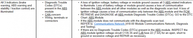
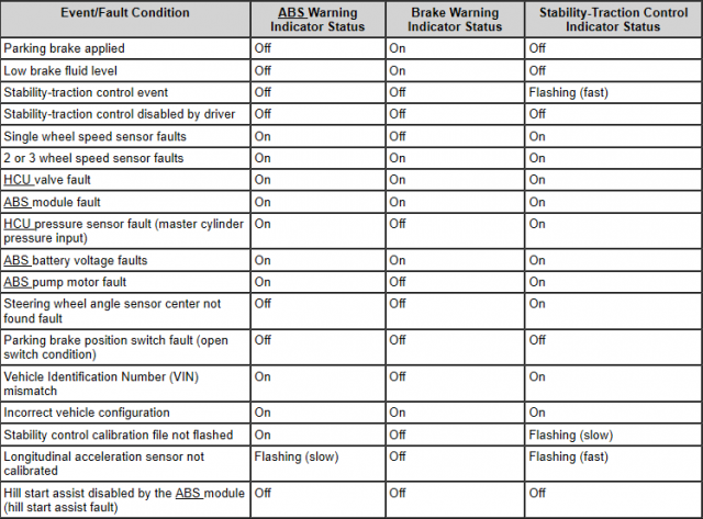
I've gone ahead and bought 2 wheel sensors... by looking at the table above I see the following things could be wrong:
2 or 3 wheel speed sensor faults (I still think this is unlikely but we'll see)
HCU valve fault
ABS module fault
ABS battery voltage faults
Incorrect vehicle configuration
I spent all day yesterday trying to clean the wheel speed sensors and they just looked great to me, heck they were working just fine when I got the car. The harness I replaced also looks good to me so I'm out of ideas. I even got this multi-meter but I'm either not using right or it's just pointless at trouble shooting stuff. I took it out again for a spin and sure thing, after going over 15mph, outside temperature disappears from the screen, airbag light goes off and power steering fault error pops up on the screen. The Power steering error goes away after you slow down.
The Bluedriver scan tool comes back with U0121 "Lost communication with Anti Lock Brake System Control Module"
At this point I'm thinking about having to re-do the whole wiring harness or take it to Ford for an ABS reprogramming but I sure don't want to pay that much for that... Does anyone have any ideas?
I tried clearing codes again and while the P1934 has not come back I suspect it will soon since I still have ABS, Traction control and Brake lights on. This is what I found on the workshop manual:
I've gone ahead and bought 2 wheel sensors... by looking at the table above I see the following things could be wrong:
2 or 3 wheel speed sensor faults (I still think this is unlikely but we'll see)
HCU valve fault
ABS module fault
ABS battery voltage faults
Incorrect vehicle configuration
I spent all day yesterday trying to clean the wheel speed sensors and they just looked great to me, heck they were working just fine when I got the car. The harness I replaced also looks good to me so I'm out of ideas. I even got this multi-meter but I'm either not using right or it's just pointless at trouble shooting stuff. I took it out again for a spin and sure thing, after going over 15mph, outside temperature disappears from the screen, airbag light goes off and power steering fault error pops up on the screen. The Power steering error goes away after you slow down.
The Bluedriver scan tool comes back with U0121 "Lost communication with Anti Lock Brake System Control Module"
At this point I'm thinking about having to re-do the whole wiring harness or take it to Ford for an ABS reprogramming but I sure don't want to pay that much for that... Does anyone have any ideas?
Thread Starter
#27
I wonder if the steering rack took a knock in the crash. Have you re centered the steering wheel? Also did you double check your grounds? Perhaps a connector isnt all the way in
Thread Starter
#28
What are the codes set for the ABS module? That is a completely different system from the PCM/ECM codes. You also must have a scantool program that can read ABS and SRS codes.
Sent from my SM-N950U1 using Tapatalk
Sent from my SM-N950U1 using Tapatalk
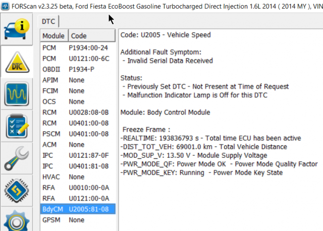
Nothing from the ABS module which I found interesting as the ABS module doesn't even show up. Maybe the car is not connecting with the ABS module at all and that's what is causing this whole mess?
Below are the codes and what they say:
Code: P1934 - Vehicle Speed Signal
Status:
- DTC Maturing - Intermittent at Time of Request
- Malfunction Indicator Lamp is Off for this DTC
Module: Powertrain Control Module
Code: U0121 - Lost Communication With Anti-Lock Brake System (ABS) Control Module A
Status:
- DTC Maturing - Intermittent at Time of Request
- Malfunction Indicator Lamp is Off for this DTC
- Test not complete
Module: Powertrain Control Module
Code: P1934 - Vehicle Speed Signal
Status:
- Pending - malfunction is expected to be confirmed
Module: On Board Diagnostic II
Code: U0028 - Vehicle Communication Bus A
Additional Fault Symptom:
- Bus Signal/Message Failures
Status:
- DTC Present at Time of Request
- Malfunction Indicator Lamp is Off for this DTC
Module: Restraint Control Module
Code: U0401 - Invalid Data Received from ECM/PCM A
Status:
- Previously Set DTC - Not Present at Time of Request
- Malfunction Indicator Lamp is Off for this DTC
Module: Restraint Control Module
Code: U0401 - Invalid Data Received from ECM/PCM A
Status:
- Previously Set DTC - Not Present at Time of Request
- Malfunction Indicator Lamp is Off for this DTC
Module: Power Steering Control Module
Code: U0121 - Lost Communication With Anti-Lock Brake System (ABS) Control Module A
Additional Fault Symptom:
- Missing Message
Status:
- DTC Present at Time of Request
- Malfunction Indicator Lamp is Off for this DTC
Module: Instrument Panel Control Module
Code: U0401 - Invalid Data Received from ECM/PCM A
Additional Fault Symptom:
- Invalid Serial Data Received
Status:
- Previously Set DTC - Not Present at Time of Request
- Malfunction Indicator Lamp is Off for this DTC
Module: Instrument Panel Control Module
Code: U0010 - Medium Speed CAN Communication Bus
Status:
- DTC Present at Time of Request
- Malfunction Indicator Lamp is Off for this DTC
Module: Remote Function Actuator
Code: U0121 - Lost Communication With Anti-Lock Brake System (ABS) Control Module A
Status:
- DTC Present at Time of Request
- Malfunction Indicator Lamp is Off for this DTC
Module: Remote Function Actuator
Code: U2005 - Vehicle Speed
Additional Fault Symptom:
- Invalid Serial Data Received
Status:
- Previously Set DTC - Not Present at Time of Request
- Malfunction Indicator Lamp is Off for this DTC
Module: Body Control Module
Freeze Frame :
-REALTIME: 193836793 s - Total time ECU has been active
-DIST_TOT_VEH: 69001.0 km - Total Vehicle Distance
-MOD_SUP_V: 13.50 V - Module Supply Voltage
-PWR_MODE_QF: Power Mode OK - Power Mode Quality Factor
-PWR_MODE_KEY: Running - Power Mode Key State
It very well could be. The electric rack, and abs/stability/traction control communicate with the abs module. Maybe check for a popped fuse for the abs system? Always a good idea to start simple.
Thread Starter
#30
It very well could be. The electric rack, and abs/stability/traction control communicate with the abs module. Maybe check for a popped fuse for the abs system? Always a good idea to start simple.
I think the PCM/ECM will have to be re-flashed due to the fact it may be a Can-bus network system. In CAN-BUS systems when introducing new parts the computer needs to be told that its been replaced. weird I know. But with some of the cars I've worked on especially Chrysler LLC vehicles with can-bus are really sensitive with certain components. You would have to go in and re-flash the computer to let it know there was a new part introduced.
I think the PCM/ECM will have to be re-flashed due to the fact it may be a Can-bus network system. In CAN-BUS systems when introducing new parts the computer needs to be told that its been replaced. weird I know. But with some of the cars I've worked on especially Chrysler LLC vehicles with can-bus are really sensitive with certain components. You would have to go in and re-flash the computer to let it know there was a new part introduced.
I haven't had the opportunity to run through ForScan features but if it offers a network test I would try to do that first and foremost though. But I have seen some impressive datalogging capabilities from ForScan so you might also want to view your wheel speed sensor signals as they are spun up to check for missing/breaking signals if possible.
Sent from my LGLS990 using Tapatalk
Thread Starter
#36
I think the PCM/ECM will have to be re-flashed due to the fact it may be a Can-bus network system. In CAN-BUS systems when introducing new parts the computer needs to be told that its been replaced. weird I know. But with some of the cars I've worked on especially Chrysler LLC vehicles with can-bus are really sensitive with certain components. You would have to go in and re-flash the computer to let it know there was a new part introduced.
Is the reflashing something I can do myself with Forscan or will I have to bring it into the dealership? I tried looking for the ABS module in Forscan and it's just not there, it doesn't even throw any DTCs.
Thread Starter
#37
This is exactly where to start IMO. Any major work done could result in serious miscommunication between new parts and old modules. The workshop manual recommends doing a programmable module installation (PMI) after major repairs, so you could do this on the ABS module, Body Control Module (BCM) and the instrument panel cluster module (IPC) *after* your repairs are done. You might also check for an updated PCM calibration after that. Unfortunately this probably requires IDS and a VCM.
I haven't had the opportunity to run through ForScan features but if it offers a network test I would try to do that first and foremost though. But I have seen some impressive datalogging capabilities from ForScan so you might also want to view your wheel speed sensor signals as they are spun up to check for missing/breaking signals if possible.
Sent from my LGLS990 using Tapatalk
That's unfortunate that the WSS signals can't be logged with ForScan.
If you are still not getting communication to/from the ABS module it might actually be the module communications network. Those wires you have pictured as damaged in one of your earliest posts (#2 picture 2) specifically VDB04 (White with blue stripe) and VDB05 (White, not pictured) are for the HSCAN communications network between the PSCM (Power steering control module), IPC (Instrument Panel Cluster), RFA (Remote function actuator), ABS, RCM (Restraints control module), and your PCM. If there was an issue in communication between all of these modules due to the physical wiring it could explain most if not all of your current issues.
That picture in post #2 image 2 is concerning because of the bare metal and exposed wiring from the insulation being crushed. If the communications wire shorted to the body that way, the result couldn't be good. It may have wreaked havoc on the modules in that network, but that's getting into conjecture at that point.
Sent from my LGLS990 using Tapatalk
Edit: cleared up a couple of things
Last edited:
Thread Starter
#39
That's unfortunate that the WSS signals can't be logged with ForScan.
If you are still not getting communication to/from the ABS module it might actually be the module communications network. Those wires you have pictured as damaged in one of your earliest posts (#2 picture 2) specifically VDB04 (White with blue stripe) and VDB05 (White, not pictured) are for the HSCAN communications network between the PSCM (Power steering control module), IPC (Instrument Panel Cluster), RFA (Remote function actuator), ABS, RCM (Restraints control module), and your PCM. If there was an issue in communication between all of these modules due to the physical wiring it could explain most if not all of your current issues.
That picture in post #2 image 2 is concerning because of the bare metal and exposed wiring from the insulation being crushed. If the communications wire shorted to the body that way, the result couldn't be good. It may have wreaked havoc on the modules in that network, but that's getting into conjecture at that point.
Sent from my LGLS990 using Tapatalk
Edit: cleared up a couple of things
If you are still not getting communication to/from the ABS module it might actually be the module communications network. Those wires you have pictured as damaged in one of your earliest posts (#2 picture 2) specifically VDB04 (White with blue stripe) and VDB05 (White, not pictured) are for the HSCAN communications network between the PSCM (Power steering control module), IPC (Instrument Panel Cluster), RFA (Remote function actuator), ABS, RCM (Restraints control module), and your PCM. If there was an issue in communication between all of these modules due to the physical wiring it could explain most if not all of your current issues.
That picture in post #2 image 2 is concerning because of the bare metal and exposed wiring from the insulation being crushed. If the communications wire shorted to the body that way, the result couldn't be good. It may have wreaked havoc on the modules in that network, but that's getting into conjecture at that point.
Sent from my LGLS990 using Tapatalk
Edit: cleared up a couple of things
I also checked the fuses and all of them were good.
Next, I went to B2 (and B3 since B3 didn't work out) where I checked for resistance. While I think I did this right, getting the negative lead plugged into the data link connector (for step B3) and the positive into the ABS connector was a challenge as I didn't have long enough cables so I had to "extend" the ones I had with wires I had laying around.
Not sure the best way to check for resistance but while I was seeing spikes of 30-140 while trying to put the lead into the connector, once it was secured and touching, I was getting close to 0 ohms. So I don't think this is the problem
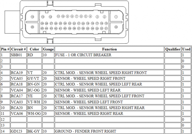
Lastly, I went over B4 and everything seemed right other than not working.
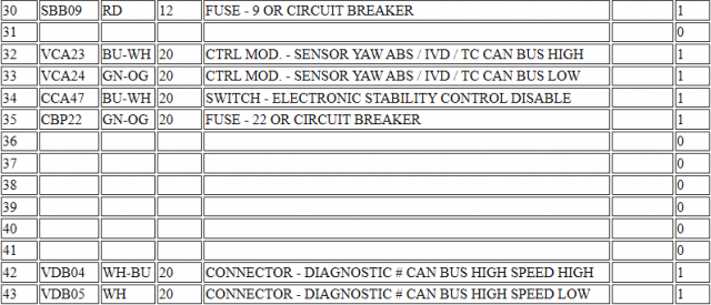
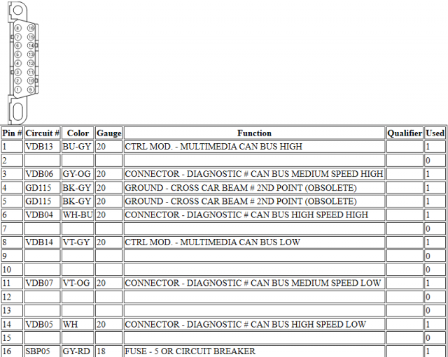
These are the connectors and what each pin means
And for the Data link connector:
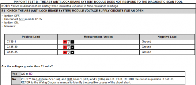
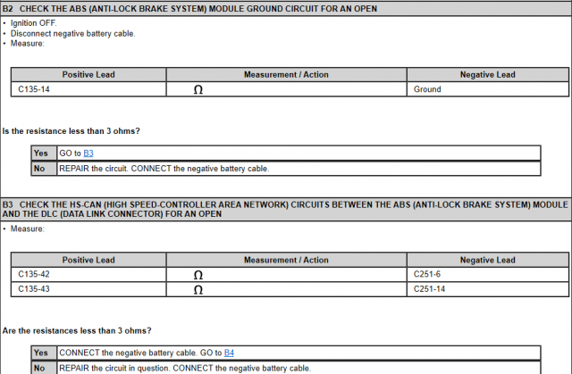
All those wires are part of the engine compartment wiring harness which was replaced (see post #4). I grabbed the workshop manual where they explain what to do to troubleshoot the ABS module if this one is not responding. I checked for voltage in the ABS module connector and I was getting a solid 12V from each one of the pins they wanted me to check:
View attachment 24326
I also checked the fuses and all of them were good.
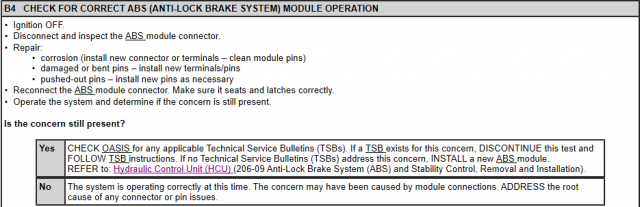
Next, I went to B2 (and B3 since B3 didn't work out) where I checked for resistance. While I think I did this right, getting the negative lead plugged into the data link connector (for step B3) and the positive into the ABS connector was a challenge as I didn't have long enough cables so I had to "extend" the ones I had with wires I had laying around.
Not sure the best way to check for resistance but while I was seeing spikes of 30-140 while trying to put the lead into the connector, once it was secured and touching, I was getting close to 0 ohms. So I don't think this is the problem
View attachment 24327
Lastly, I went over B4 and everything seemed right other than not working.
View attachment 24328
These are the connectors and what each pin means
View attachment 24329
View attachment 24330
And for the Data link connector:
View attachment 24331
View attachment 24326
I also checked the fuses and all of them were good.
Next, I went to B2 (and B3 since B3 didn't work out) where I checked for resistance. While I think I did this right, getting the negative lead plugged into the data link connector (for step B3) and the positive into the ABS connector was a challenge as I didn't have long enough cables so I had to "extend" the ones I had with wires I had laying around.
Not sure the best way to check for resistance but while I was seeing spikes of 30-140 while trying to put the lead into the connector, once it was secured and touching, I was getting close to 0 ohms. So I don't think this is the problem
View attachment 24327
Lastly, I went over B4 and everything seemed right other than not working.
View attachment 24328
These are the connectors and what each pin means
View attachment 24329
View attachment 24330
And for the Data link connector:
View attachment 24331
Sent from my SM-G930P using Tapatalk
Similar threads
-
-
-
-
 Rebuilding the Transmission in my 2014 FiST
- Started by sluggyjunx
- Replies: 18
-
 Tjin Edition - Ford Fiesta ST - SEMA Project -
- Started by grip grip
- Replies: 15
-
-
 F/S: Tjin Edition / aLL STaR Ford Fiesta ST SEMA Project
- Started by aLL STaR Fiesta ST
- Replies: 25